Veterobot Project
DESIGNED BY :
This project is a robotic vehicle which you can print with your 3d Printer (you can download .STL files for this project)
In this project we will focus on sensors, connectivity, software, vision and lots of fields of Robotic.
Target audience of Veterobot
At the first step we are targeting researches in robotics, artificial intelligence and computer vision as well as hobby robotics enthusiasts. For this purposes, we identified and addressed the following key requirements:
-should be complete open (hardware and software)
-equipped with typical and widely used set of sensors
-easy customizable to integrate new or different types of sensors and actuators
-energy efficient yet powerful on-board computer
-provide bi-directional communication link to transmit sensor and control data in real-time
-set of software modules which support distributed data processing and provide hardware abstraction layer.
-considerably lower cost comparing to the similar available products
Chassis and body

We are using Dagu Rover 5 Tracked Chassis with two motors and two quadrature encoders.
The whole body is 3D-printed and provides:
– rotated “head” (to mount camera on it)
– folding mast for EMS-sensitive sensors (such as, for example, digital compass)
– place for exchangeable batteries
– “doors” to access the inside electronic connectors
– extension options for additional electronic, sensors and actuators
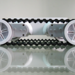
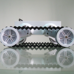
Application of the 3D printing significantly simplifies customization of the body. In addition, it opens the natural way to integrate new types of sensors and actuators. All 3D models are developed using popular open-source modeling tool Blender. All the models required to print the body are also available as open-source. The following set of pictures provides some examples:


The first two pictures shows our current model and the last two represent rendered 3D models of the alternative bodies we are currently working on.
Sensors and on-board electronic
In the full configuration the following sensors are available:
- four ultra-sound range finders (on the sides, front and back)
- two video cameras
- pan/tilt compensated digital compass
- GPS receiver
The front sonar and cameras could be mounted on the “head” which is rotated by the servo motor. All peripheral devices are connected to the on-board computer over USB and connectors provided by the daughter board. Current robot version uses TI’s BeagleBoard-xM as on-board computer. BeagleBoard is an open-hardware embedded computer with dual-core CPU (ARM+DSP). It provides enough power to compress video stream with H.264 codec in real-time, control the hardware and run advanced navigation algorithms. We are using standard in modeling domain Nigh batteries. For development, the robot could be powered with external power supply.
Connectivity
Robot is equipped with the IEEE 802.11 b/g/n WLAN-Adapter. Currently, we are testing the operation mode with 3G-Modem (UMTS). It is already possible (there is an available software) to remotely control the robot over the Internet using real-time video streaming from on-board camera. Of course, the autonomous operation mode is also possible. In particular, we support cloud-robotics paradigm: complex navigation algorithms could be executed on external powerful computer if the on-board computer does not provide enough performance.

Software
The whole software is open-source and is available on git-hub. We offer the complete stack from operating system up to communication infrastructure and client-side user interface and visualization applications.
- -We provide customized image based on popular Angstrom Linux distribution which is optimized for the the BeagleBoard.
- -We are using Xenomai Linux real-time extension for motor control and other time-sensitive tasks.
- -Sensors and actuators are remotely accessible (over the network) using corresponding software components.
- for all remoting purposes we are using ZeroC’s Ice (Internet Communication Engine) middleware.
- it allows developers to use wide range of programming languages (C++, Python, Ruby, Java and all .Net-languages) to develop own software components.
- Ice also supports different communication paradigms such as for example Publisher/Subscriber, RPC-stile remote invocations, etc. It provides great flexibility for developers when designing own software components.
There is an OpenGL-based application “cockpit” available to remotely control the robot manually. Sensor data (including video from cameras) are rendered in real-time and control commands are sent back to the vehicle. Keyboard and USB joysticks are supported as control devices. The following picture illustrate the current version of the cockpit application.
To demonstrate how to develop solutions for typical problems from robotics domain using our platform we implement several homework assignments from “Programming A Robotic Car” online course taught by Prof. Sebastian Thrun. These examples illustrates the applicability of our platform in educational domain. In particular, comparing to popular LEGO Mindstorms systems, our system offers more computational power and more flexible set of software building blocks to solve typical robotics problems. Cloud-robotics and distributed autonomous robotic systems are promising future directions. Our platform is the step towards this direction and our customers could benefit by reusing our software and hardware and concentrate on their areas of competence.
MAIN STEPS
We are constantly developing and improving our robot. As a result, the building instructions could quickly become outdated. However, our project wiki is kept up to date. That is why we decide to provide here high-level overview of required steps and refer to the corresponding wiki articles for more details.
If you decide to build the robot yourself, here are the main steps to accomplish:
STEP 1 – 3D print the robot’s body.
Currently we are using Ultimaker 3D printer. All the models (original Blender files and generated STL files) are freely available from our git repository.
Download 3d Files for parts of the image below:

For This Project Web Site: – http://veterobot.com/
For Assembly Instructions: – https://github.com/veter-team/veter/wiki/assembling
This Project’s Blog: http://veter-project.blogspot.com/