Category: LEARN ROBOTICS

Watt straight-line mechanism

Linkages – Watts Straight Line 51016

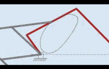
Watt’s straight-line generator, can describe a short vertical straight line. Equal length links AB and CD are hinged at A and D, respectively. The midpoint E of connecting link BC traces a figure eight pattern over the full mechanism excursion, but a straight line is traced in part of the excursion because point E diverges to the left at the top of the stroke and to the right at the bottom of the stroke. This linkage was used by Scottish instrument maker, James Watt, in a steam-driven beam pump in about 1769, and it was a prominent mechanism in early steam-powered machines.

Linkages – Tchebicheff Straight Line 51015

Tchebicheff’s straight-line generator, can also describe a horizontal line. Link CB with E as its midpoint traces a straight horizontal line for most of its transit as links AB and DC are moved to the left and right of center. To describe this straight line, the length of the foundation link AD must be twice the length of link CB. To make this mechanism work as a straight-line generator, CB is 10 units long,

AD is 20 units long, and both AB and DC are 25 units long. With these dimensions, link CB will assume a vertical position when it is at the right and left extremes of its travel excursion. This linkage was invented by nineteenth-century Russian mathematician, Pafnuty Tchebicheff or Chebyshev.

Peaucellier's linkage (www.howround.com)

Linkages – PEAUCELLIER CELL 51014

The PeaucellierLipkin linkage (or Peaucellier–Lipkin cell, or Peaucellier–Lipkin Inversor), invented in 1864, was the first planar linkage capable of transforming rotary motion into perfect straight-line motion, and vice versa. It is named after Charles-Nicolas Peaucellier (1832–1913), a French army officer, and Yom Tov Lipman Lipkin, a Lithuanian Jew and son of the famed Rabbi Israel Salanter.

Linkages – EVANS STRAIGHT LINE 51013

A mechanism that produces a straight-line (or nearly so) output motion from an input element that rotates, oscillates, or moves in a straight line. Common machine elements, such as linkages, gears, and cams, are often used in ingenious ways to produce the required controlled motion. The more elegant designs use the properties of special points on one of the links of a four-bar linkage.

Pantograph - copying a path of point on a coupler of four bar linkage

Mechanisms – Linkages – Pantograph Mechanism – 51012

A pantograph is a mechanical linkage connected in a manner based on parallelograms so that the movement of one pen, in tracing an image, produces identical movements in a second pen. If a line drawing is traced by the first point, an identical, enlarged, or miniaturized copy will be drawn by a pen fixed to the other.

Because of their effectiveness at translating motion in a controlled fashion, pantographs have come to be used as a type of motion guide for objects large and small. A common example of the use of a pantograph assembly as mechanical guide frame is the extension arm of an adjustable wall-mounted mirror.

FIRM Research Project: Hoekens Linkage (Algodoo)

Four Bar Linkages – Hoekens Linkage – 51011

The Hoekens linkage is a four-bar mechanism that converts rotational motion to approximate straight-line motion with approximate constant velocity. The precise design trades off straightness, lack of acceleration, and what proportion of the driving rotation is spent in the linear portion of the full curve.

Four-Bar Linkages

Robotic Mechanisms – Four Bar Linkages 51010

What are Complex Linkages ? Four Bar Linkages ?

In addition to changing the motions of objects or forces, more complex linkages have been designed to perform many specialized functions: These include;
-drawing or tracing straight lines;
-moving objects or tools faster in a retraction stroke than in an extension stroke;
-and converting rotating motion into linear motion and vice versa.

What is a Lever? Simple Machines | Mocomi Kids

Robotic MECHANISMS – LEVERS 51008

What is a Lever ? Types of Levers…

Levers are the simplest of mechanisms; there is evidence that Stone Age humans used levers to extend their reach or power; they made them from logs or branches to move heavy loads such as rocks. It has also been reported that primates and certain birds use twigs or sticks to extend their reach and act as tools to assist them in obtaining food.

A lever is a rigid beam that can rotate about a fixed point along its length called the fulcrum. Physical effort applied to one end of the beam will move a load at the other end. The act of moving the fulcrum of a long beam nearer to the load permits a large load to be lifted with minimal effort. This is another way to obtain mechanical advantage.

The three classes of lever are illustrated in Fig. Each is capable of providing a different level of mechanical advantage. These levers are called Class 1, Class 2, and Class 3. The differences in the classes are determined by:

Efficiency of Machines & Mechanical Advantage 51006

EFFICIENCY of MACHINES

Simple machines are evaluated on the basis of efficiency and mechanical advantage. While it is possible to obtain a larger force from a machine than the force exerted upon it, this refers only to force and not energy; according to the law of conservation of energy, “more work cannot be obtained from a machine than the energy supplied to it”.